Lattices
Introduction to lattices
Lattices create repeated structures on a mesh defined with a rectangular or triangular pitch.
Note
At most one lattice is allowed per module. However, it is possible to describe lattices of lattices by combining multiple modules.
Note
In addition to simplifying the modeling, using a lattice is also CPU time efficient.
A lattice consists of two components:
a mesh volume
a lattice volume
The mesh volume is the repeated unit. It is specified once in the data-set and the code will replicate it as many times as necessary.
Note that a mesh volume is strictly prohibited from:
intersecting or being intersected by another volume (no use of the
INTEkeyword);overwriting or being overwritten by another volume (no use of the
SUPEorINFEkeywords);being in union with another volume (no use of the
UNIOkeyword);being truncated (no use of the
TRUNkeyword) - but it is allowed to truncate a volume.
The lattice volume is the volume that encompasses the entire lattice and contains all the mesh volumes. The lattice volume can:
have any finite shape;
overwrite or be overwritten by another volume (use of the
SUPEorINFEkeywords);truncate or be truncated by another volume (use of the
TRUNkeyword);be intersected (use of the
INTEkeyword) but cannot intersect another volume.
However, a lattice volume cannot be in union with another volume (no use of the UNIO keyword).
The mesh volume must be either fully or partially contained in the lattice volume.
Geometrical operations such as overwriting, truncation or intersection on a lattice volume are automatically applied to its mesh volumes.
Note
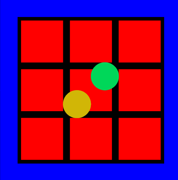
Volumes other than mesh volumes are allowed inside the lattice volume, provided they are directly contained within it. In this case, they replace the mesh volumes they interact with, as demonstrated in the following example:
Example of other volumes inside the Lattice volume
In this example two spheres (in orange and green) overwrite the lattice in two different ways:
Volume 5 has the lattice volume as its parent (it is directly included in the lattice);
Volume 6 does not have the lattice volume as its parent but uses the
SUPEkeyword to overwrite the lattice.
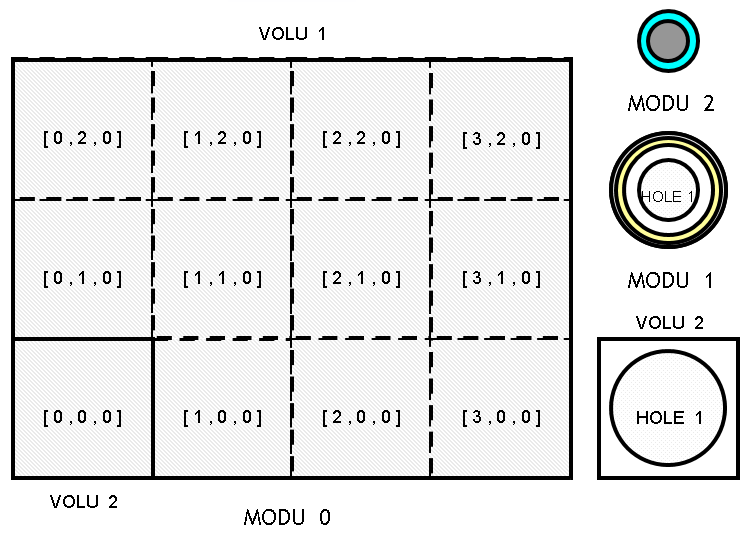
* The following example represents a lattice whose dimensions are [3, 3, 1]:
* - the volume 2 is the lattice volume;
* - the volume 3 is the main mesh volume which contains the volume 4;
* Volumes 5 and 6 overwrites some volumes of the lattice with two different ways.

GEOM
  MODU 0
    * External volume
    TYPE 1 BOX 13 13 25.0
    VOLU 1 0 1 water 0. 0. 0.

    * Lattice volume
    TYPE 2 BOX 10.5 10.5 25.0
    VOLU 2 1 2 concrete 0. 0. 0.

    * Mesh volume
    TYPE 3 BOX 3.5 3.5 25.0
    VOLU 3 2 3 concrete -7.0 -7.0 0.0

    * Volume inside mesh volume
    TYPE 4  BOX 3.0 3.0 25.
    VOLU 4  3 4 fissile -7.0 -7.0 0.0

    * Lattice
    LATS
      MPRI 3
        DIML 3 3 1
        INDP 1 1 1
    ENDL

    * Volume 5 is directly included in the lattice
    TYPE 5 SPHE 2.
    VOLU 5 2 5 water_v5 2. 2. 0.

    * Volume 6 is SUPE to the lattice
    TYPE 6 SPHE 2.
    VOLU 6 1 6 water_v6 -2. -2. 0. SUPE (2)

  ENDM
ENDG
Lattice creation
The creation of a lattice requires at least the definition of:
a rectangular or triangular lattice pitch (
LATSorLATHkeywords);a main mesh volume (
MPRIkeyword);the dimensions of the lattice (
DIMLkeyword).
Lattice type
(LATS | LATH )
  (..)
ENDL
Use the LATS keyword to define a rectangular pitch. In this case, the mesh volumes must be parallelepipeds (BOX or LBOX keywords).
These mesh volumes are then juxtaposed to form a larger rectangular parallelepiped;
Use the LATH keyword to define a triangular pitch. In this case, mesh volumes must be hexagons aligned with the Z-axis (using the HEXZ keyword).
These mesh volumes are then juxtaposed to form several rings of hexagons along the X-axis and Y-axis, and several layers along the Z-axis.
The following figures illustrate the two types of lattices:

Main mesh volume
The MPRI keyword defines the main mesh volume of the lattice.
MPRI id-mesh
The initial position of this main mesh volume is determined by the index [0, 0, 0] (which corresponds to the first element of the main mesh volume).
This “origin” index can be adjusted using the INDP keyword.
Regardless of the mesh volume’s position, the lattice is constructed by replicating the main mesh volume, starting from its defined location within the module.
Lattice dimensions
The DIML keyword defines the size of the lattice.
DIML ( nx ny nz | nc nz )
Input parameter |
Lattice pitch |
Description |
|---|---|---|
nx ny nz |
Rectangular |
Lattice size along the three axes. |
nc |
Triangular |
Lattice radial size (i.e. the number or rings) |
nz |
Triangular |
Lattice size along the Z-axis |
A negative value means that volumes are replicated up to the limits of the lattice volume.
A positive value with a rectangular lattice indicate the number of mesh volumes in the growth direction. The volume defined as the main mesh volume has the minimum coordinates in the corresponding direction.
In case of a triangular lattice, a positive value means:
horizontal axis: number of rings around the main mesh volume. The central mesh is considered the first ring.
vertical axis: number of layers in the growth direction Z.
The main mesh volume has the [ 0, 0, 0 ] index and the other mesh volumes are numbered according to this origin and to the type of lattice.
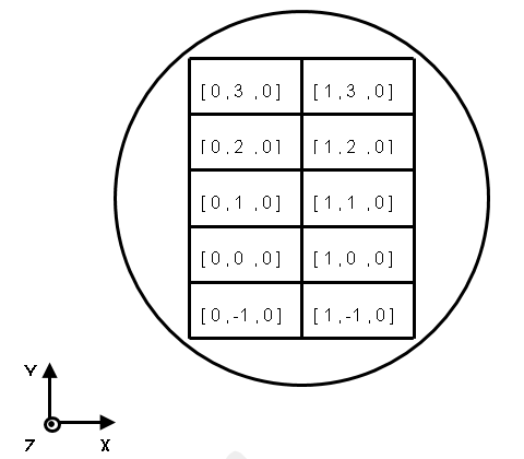
Numbering of a rectangular lattice
For a rectangular pitch, each index increases along its respective reference axis.
LATS
  MPRI …
  DIML 3 2 3
ENDL

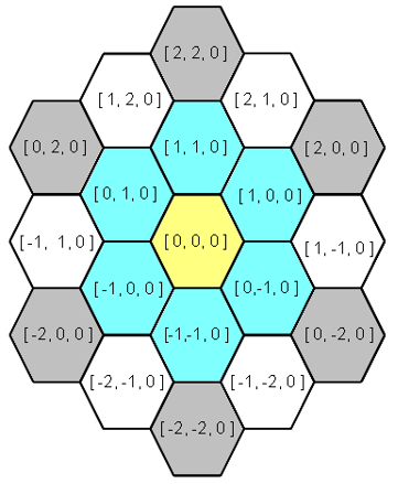
Numbering of triangular lattice
For a triangular pitch, the mesh volumes are numbered using another set of reference axes (O; X’, Y’, Z):
the (OX’) axis is perpendicular to sides 1 and 4 of the main mesh volume;
the (OY’) axis is perpendicular to sides 3 and 6 of the main mesh volume;
the (OZ) axis remains unchanged.
LATH
  MPRI …
  DIML
ENDL

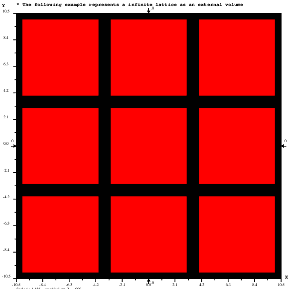
Example of lattice with negative DIML values
* Lattice dimensions are not specified.
* M6Geo determines the number of meshes to be placed.
* In this example 3 in each of the tree axes

GEOM
  MODU 0

    * Lattice volume (external volume)
    TYPE 2 BOX 10.5 10.5 6.0
    VOLU 2 0 2 concrete 0. 0. 0.

    * Mesh volume
    TYPE 3 BOX 3.5 3.5 2.
    VOLU 3 2 3 concrete 0.0 0.0 0.0

    * Volume inside mesh volume
    TYPE 4  BOX 3.0 3.0 2.
    VOLU 4  3 4 fissile 0.0 0.0 0.0

    * Lattice
    LATS
      MPRI 3
        DIML -1 -1 -1 * infinite lattice in all direction
    ENDL

  ENDM
ENDG
Properties of the mesh volume
Mesh indices
The INDP keyword redefines the mesh volumes numbering.
INDP ix iy iz
Input parameter |
Description |
|---|---|
ix iy iz |
Indices of the main mesh volume (default 0, 0, 0) |
The first main mesh volume will be positioned at the [ix, iy, iz] index as specified by the user. Subsequent mesh volumes will be numbered based on this new origin.
Note
The INDP keyword must be placed after the mandatory keywords and before any optional keywords.
Example of INDP
LATS
  MPRI …
  DIML 3 2 3
  INDP 3 4 5
ENDL

Secondary mesh volumes
The MSEC keyword allows the replacement of mesh volumes with alternative ones.
This keyword must be repeated for every different secondary mesh volume with alternative patterns.
MSEC id   p  ix(1)  iy(1)  iz(1)
          (…)
          ix(j)  iy(j)  iz(j)
          (…)
          ix(p)  iy(p)  iz(p)
Input parameter |
Description |
|---|---|
id |
Volume identifier of the secondary mesh volume |
p |
Number of mesh volumes containing the volume id-msec |
ix(j) iy(j) iz(j) |
Indices of the mesh volume j for which a secondary mesh volume is used instead of the main mesh volume |
The following constraints apply to the secondary mesh volume:
its parent volume must be the lattice volume;
its type identifier (
TYPEkeyword) must be the same as the main mesh volume;its position in the geometry must be the same as the main mesh volume.
Note
This keyword must appear both after the lattice mandatory keywords and after the INDP keyword (if defined).
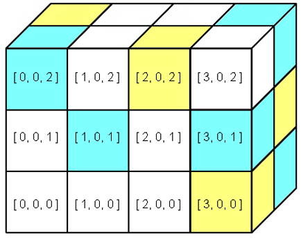
Example for a rectangular lattice
* The example illustrates the MSEC keyword in the case of a rectangular lattice.
* The main mesh color is white.
* The mesh with indices:
* [0, 0, 2]
* [1, 0, 1]
* [3, 0, 1]
* [3, 1, 0]
* [3, 1, 2]
* are in blue
* The mesh with indices:
* [0, 1, 2]
* [2, 0, 2]
* [3, 0, 0]
* [3, 1, 1]
* are in yellow

GEOM
  MODU 0
    * Lattice volume
    TYPE  2  BOX   4. 2. 3.
    VOLU v2  0  2 m2  4. 2. 3.
    * Main mesh volume
    TYPE  3  BOX  1. 1. 1.
    VOLU v3 v2  3 m3 1. 1. 1.  * green
    * Secondary mesh volumes
    VOLU v4 v2  3 m4 1. 1. 1.  * blue
    VOLU v5 v2  3 m5 1. 1. 1.  * yellow
    * Definition of the lattice
    LATS
     MPRI v3
     DIML  4  2  3
     MSEC v4  (  0  0  2
                 1  0  1
                 3  0  1
                 3  1  0
                 3  1  2 )
     MSEC v5  4  0  1  2
                 2  0  2
                 3  0  0
                 3  1  1
    ENDL
  ENDM
ENDG

Example for a triangular lattice pitch
* The example illustrates the MSEC keyword in the case of a triangular pitch lattice.
* The main mesh color is green.

GEOM

MODU 0

  * Lattice volume
  TYPE  2  BOX 10. 10. 10.
  VOLU  2  0  2  m2  0. 0. 0.
  * Main mesh volume
  TYPE  3  HEXZ  2. 10. 0.
  VOLU  3  2  3  m3 0. 0. 0.  * green
  * Secondary mesh volumes
  VOLU  4  2  3  m4 0. 0. 0.  * blue
  VOLU  5  2  3  m5 0. 0. 0.  * yellow
  VOLU  6  2  3  m6 0. 0. 0.  * grey
  * Definition of the lattice
  LATH
   MPRI  3
   DIML  3  1
   MSEC  4  6   1   0   0  * blue
                1   1   0  * blue
                0   1   0  * blue
               -1   0   0  * blue
               -1  -1   0  * blue
                0  -1   0  * blue
   MSEC  5  1   0   0   0  * yellow
   MSEC  6  6   2   0   0  * grey
                2   2   0  * grey
                0   2   0  * grey
               -2   0   0  * grey
               -2  -2   0  * grey
                0  -2   0  * grey
  ENDL


ENDM

ENDG
The resulting plot, with the lattice axes indicated by dashed lines, is shown below:

Secondary mesh as layers
The LAYE keyword provides an alternative method for defining mesh volumes.
It allows the user to specify the volume identifiers of each mesh volume for a given layer along the Z-axis.
To use this keyword, lattice dimensions (DIML keyword) must be positive values for the horizontal directions (i.e. directions parallel to the (O; X; Y) plane of the reference frame).
LAYE k  id(i-min, j-min, k) (..) id(i-max, j-max, k)
        (..)
        id(i-min, j-min, k) (..) id(i-max, j-max, k)
Input parameter |
Description |
|---|---|
k |
Index of the layer to be modified along the Z-axis |
id(i, j, k) |
Identifier of the Volume used for the mesh volume (either main or secondary) with indices [ i, j, k ]. The indices i and j vary from their minimum to maximum value. The k index is a constant value equal to the first argument of the keyword |
Note
This keyword must appear both after the lattice mandatory keywords and after the INDP keyword (if defined).
The following constraints apply to each secondary mesh volume used in the layer:
its parent volume must be the lattice volume;
its type identifier (
TYPEkeyword) must be the same as the main mesh volume;its position in the geometry must be the same as the main mesh volume.
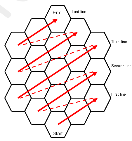
The following figure illustrates the order of volume identifiers for mesh volumes in the case of a triangular lattice.
Example for a rectangular lattice
* The example illustrates the LAYE keyword in the case of a rectangular lattice.

GEOM

MODU 0

  * Lattice volume
  TYPE  2  BOX   4. 2. 3.
  VOLU  2  0  2 m2  4. 2. 3.
  * Main mesh volume
  TYPE  3  BOX  1. 1. 1.
  VOLU  3  2  3 m3 1. 1. 1.  * white
  * Secondary mesh volumes
  VOLU  4  2  3 m4 1. 1. 1.  * blue
  VOLU  5  2  3 m5 1. 1. 1.  * yellow
  * Definition of the lattice
  LATS
    MPRI  3
    DIML  4  2  3
    LAYE 0 3 3 3 5  * 5 in [3,0,0]
           3 3 3 4  * 4 in [3,1,0]
    LAYE 1 3 4 3 4
           3 3 3 5
    LAYE 2 4 3 5 3  * 5 in [2,0,2]
           5 3 3 4  * 4 in [3,1,2]
  ENDL

ENDM

ENDG

PAIN X 1 COLO (
  m2 GREE
  m3 WHIT
  m4 BLUE
  m5 YELL) ENDP
PAIN Y 1 ENDP
PAIN Z 1 ENDP

STOP
Example for a triangular lattice pitch
* The example illustrates the MSEC keyword in the case of a triangular pitch lattice.

GEOM

MODU 0

  * Lattice volume
  TYPE  2  BOX 10. 10. 10.
  VOLU  2  0  2  m2  0. 0. 0.
  * Main mesh volume
  TYPE  3  HEXZ  2. 10. 0.
  VOLU  3  2  3  m3 0. 0. 0.  * green
  * Secondary mesh volumes
  VOLU  4  2  3  m4 0. 0. 0.  * blue
  VOLU  5  2  3  m5 0. 0. 0.  * yellow
  VOLU  6  2  3  m6 0. 0. 0.  * white
  * Definition of the lattice
  LATH
   MPRI  3
   DIML  3  1
   LAYE  0     6   3   6
              3  4   4   3
            6  4   5   4  6
              3  4   4  3
               6   3   6
  ENDL

ENDM

ENDG

PAIN X 1 COLO (
  m2 WHIT
  m3 WHIT
  m4 BLUE
  m5 YELL
  m6 GREY) ENDP
PAIN Y 1 ENDP
PAIN Z 1 ENDP

STOP
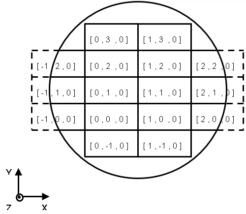
Discarding or keeping mesh volumes
The mesh volume is repeated within the space defined by the lattice volume. Any mesh volumes that overlap the lattice volume are truncated by the lattice volume itself. However, optional keywords enable the discarding or retention of specified mesh volumes:
DISMremoves a mesh volume from the lattice;DISBremoves a truncated mesh volume;KEEPretains a removed mesh volume (located within the lattice volume).
To illustrate these keywords, the following configuration will be considered in the next paragraphs. It is composed of a lattice with rectangular meshes inside a cylinder (the lattice volume):
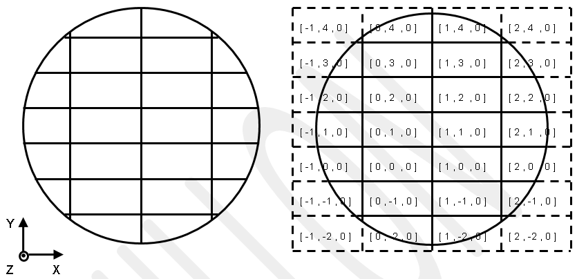
* This is a simple lattice in a cylinder
GEOM
  MODU 0
    * External volume
    TYPE 1 CYLZ 20. 1.0    VOLU 1 0 1 m1 0.  0. 0.
    * Mesh volume
    TYPE 3 BOX 5.5 3.1 1.  VOLU 3 1 3 m3 -5.5 -6.2 0.
    * Lattice
    LATS
      MPRI 3
        DIML -1 -1 1
    ENDL
  ENDM
ENDG
The DIML keyword configures the lattice such that:
it is bounded by the cylinder along the X-axis (in both directions), resulting in truncated mesh volumes;
it is bounded by the cylinder along the Y-axis (in both directions), resulting in truncated mesh volumes;
the lattice contains only one layer along the Z-axis.
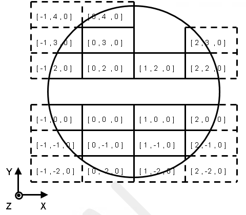
Discarding mesh
The DISM keyword removes a mesh volume from the lattice and replaces it with the material composition of the lattice volume containing it.
DISM p  ix(1) iy(1) iz(1)
        (..)
        ix(j) iy(j) iz(j)
        (..)
        ix(p) iy(p) iz(p)
Input parameter |
Description |
|---|---|
p |
Number of mesh volumes to remove |
ix(j) iy(j) iz(j) |
Indices of the jth mesh volume to remove |
Example of the DISM:
* This is a simple lattice in a cylinder with DISM
GEOM
  MODU 0
    * External volume
    TYPE 1 CYLZ 20. 1.0    VOLU 1 0 1 m1 0.  0. 0.
    * Mesh volume
    TYPE 3 BOX 5.5 3.1 1.  VOLU 3 1 3 m3 -5.5 -6.2 0.
    * Lattice
    LATS
      MPRI 3
        DIML -1 -1 1
        DISM  7  -1  1  0
                  0  1  0
                  1  1  0
                  2  1  0
                  1  3  0
                  1  4  0
                  2  4  0
    ENDL
  ENDM
ENDG
GRAP Z 0 ENDG
PAIN Z 0 ENDG
STOP
Discarding truncated mesh
The DISB keyword removes truncated mesh volumes located on the sides of a lattice.
A removed mesh volume is replaced by the material composition of the lattice volume.
By default, all truncated mesh volumes on the sides of the lattice are removed.
DISB [ BORD id-vol [ FACE p if(1) (..) if(p) ] ]
Input parameter |
Description |
|---|---|
|
Volume identifier from which incomplete mesh volumes located on its sides are to be removed. |
|
List of faces whose incomplete mesh volumes must be removed |
p |
Number of faces of the Volume to be treated |
if(1) (..) if(p) |
Volume faces identifiers |
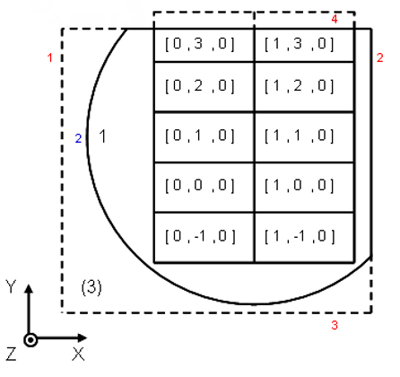
Optional keywords allow to select more precisely the mesh volumes to remove:
The
BORDkeyword, without any options, removes all truncated mesh volumes on the sides of the lattice for which the volume characterized by the id-vol identifier is the neighboring volume. This neighboring volume should be either the lattice volume or any volume that truncates or intersects the lattice volume. This keyword must be repeated for each different Volume to be considered.The
FACEkeyword specifies the faces of the neighboring Volume id-vol that are common with the sides of the lattice, where the code should remove the truncated mesh volumes.The identifiers used for the Volume faces are defined in the paragraphs describing the Volume shapes.
Example with DISB keyword only
* This is a simple lattice in a cylinder with DISB
GEOM
  MODU 0
    * External volume
    TYPE 1 CYLZ 20. 1.0    VOLU 1 0 1 m1 0.  0. 0.
    * Mesh volume
    TYPE 3 BOX 5.5 3.1 1.  VOLU 3 1 3 m3 -5.5 -6.2 0.
    * Lattice
    LATS
      MPRI 3
        DIML -1 -1 1
        DISB
    ENDL
  ENDM
ENDG
Example with precise selection of discarded mesh
* This is a simple lattice in a cylinder with DISB and BORD
GEOM
  MODU 0
    * External volume
    TYPE 1 BOX 30. 30. 1.  VOLU 1 0 1 m1 0. 0. 0.
    * Lattice volume
    TYPE 2 CYLZ 20. 1.0    VOLU 2 1 2 m2 0. 0. 0. INTE 1 3
    * Volume intersecting the lattice volume
    TYPE 3 BOX 20. 20. 1.0 VOLU 3 1 3 m3 -6. -6. 0.
    * Mesh volume
    TYPE 4 BOX 5.5 3.1 1.  VOLU 4 2 4 m3 -5.5 -6.2 0.
    * Lattice
    LATS
      MPRI 4
        DIML -1 -1 1
        DISB
          BORD 2
          BORD 3 FACE 1 2
    ENDL
  ENDM
ENDG
Keeping mesh volumes
The KEEP keyword retains the truncated mesh volumes that were previously removed, especially those removed using the DISB keyword.
KEEP p  ix(1) iy(1) iz(1)
        (..)
        ix(j) iy(j) iz(j)
        (..)
        ix(p) iy(p) iz(p)
Input parameter |
Description |
|---|---|
p |
Number of mesh volumes to keep |
ix(j) iy(j) iz(j) |
Indices of the mesh volume j to keep |
* This is a simple lattice in a cylinder with DISB and KEEP
GEOM
  MODU 0
    * External volume
    TYPE 1 CYLZ 20. 1.0    VOLU 1 0 1 m1 0.  0. 0.
    * Mesh volume
    TYPE 3 BOX 5.5 3.1 1.  VOLU 3 1 3 m3 -5.5 -6.2 0.
    * Lattice
    LATS
      MPRI 3
        DIML -1 -1 1
        DISB
        KEEP 6 -1  0  0
               -1  1  0
               -1  2  0
                2  0  0
                2  1  0
                2  2  0
    ENDL
  ENDM
ENDG
Lattices examples
Definition of the configuration
In the following sections, we will explore four alternative methods for modeling the configuration depicted below.
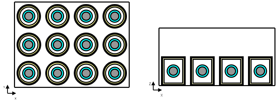
The configuration consists of a storage area containing 16 cylindrical drums stored in air (material 1). These drums form a lattice and contain fissile material (material 5) in spherical form. The details of the different components are as follows:
the storage area is a parallelepiped room filled with air;
each cylinder is filled with air and has a wall consisting of two layers: an outer steel layer (material 2) and an inner lead layer (material 3);
the fissile material is modeled as a sphere of fissile material surrounded by water (material 4).
The following modules represent the drum and the fissile sphere. They are described here to simplify the dataset used for modeling.
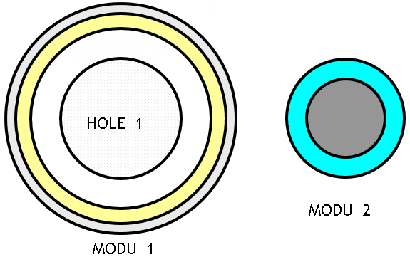
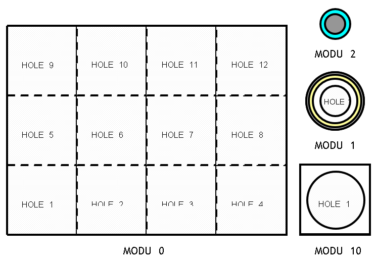
First modeling: no lattice definition
One straightforward approach is to describe this geometry without using lattice functions. In this example, four modules are used as follows:
module 0 consists of 12 Holes (module 10);
module 10 is a parallelepiped containing a cylindrical Hole (module 1);
module 1 represents a cell containing cylindrical volumes, which, in turn, includes a Hole (module 2).
module 2 represents the fissile material in the form of a sphere surrounded by water.
Input file: No lattice definition
* First modelling: no lattice definition
* A simple way to describe this geometry consists in doing so without using the lattice functions.
* In this example, we will use four modules in the following form:
* -module 0 consists of 12 holes (module 10);
* -module 10 is a parallelepiped that contains a hole whose shape is a cylinder (module 1);
* -module 1 represents a cell containing cylindrical volumes that, in its turn, contains a hole (module 2);
* -module 2 represents the fissile material in the form of a sphere surrounded by water.


GEOM

MODU M1

  * External volume
  TYPE  1  CYLZ  8. 10.
  VOLU  1  0  1  2  0. 0. 0.

  * Content
  TYPE  2  CYLZ  7.5 9.5
  VOLU  2  1  2  3  0. 0. 0.
  TYPE  3  CYLZ  7.  9.
  VOLU  3  2  3  1  0. 0. 0.

  * Hole
  TYPE  4  SPHE  5.
  HOLE  4  3  4  M2  0. 0. 0.

ENDM

MODU  M2
  TYPE  1  SPHE  5.
  VOLU  1  0  1  water  0. 0. 0.

  TYPE  2  SPHE  4.
  VOLU  2  1  2  fissile  0. 0. 0.
ENDM


MODU M10

  TYPE 1 BOX 10. 10. 20.
  VOLU 1 0 1 air 0. 0. 20.

  TYPE 2 CYLZ 8. 10.
  HOLE 1 1 2 M1 0. 0. 10.

ENDM


MODU 0

  TYPE 1 BOX 40. 30. 20.
  VOLU 1 0 1 air 0. 0. 0.

  TYPE 2 BOX 10. 10. 20.
  HOLE 11 1 2 M10 -30. -20. 0.
  HOLE 12 1 2 M10 -30.   0. 0.
  HOLE 13 1 2 M10 -30.  20. 0.

  HOLE 21 1 2 M10 -10. -20. 0.
  HOLE 22 1 2 M10 -10.   0. 0.
  HOLE 23 1 2 M10 -10.  20. 0.

  HOLE 31 1 2 M10  10. -20. 0.
  HOLE 32 1 2 M10  10.   0. 0.
  HOLE 33 1 2 M10  10.  20. 0.

  HOLE 41 1 2 M10  30. -20. 0.
  HOLE 42 1 2 M10  30.   0. 0.
  HOLE 43 1 2 M10  30.  20. 0.


ENDM

ENDG
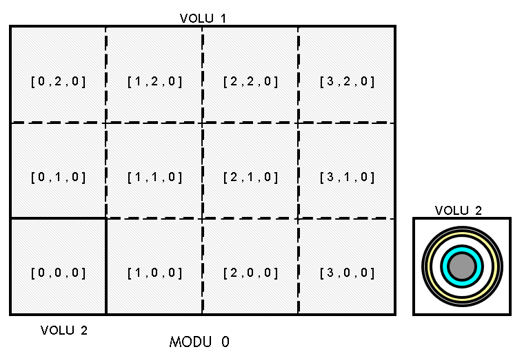
Second modeling: definition of a single lattice
An alternative method involves using a lattice whose dimensions are [4, 3, 1], where the main mesh volume is a box containing the cylinders and the spheres. In this example, only one module is used.
Input file: Definition of a single lattice
GEOM

MODU 0

  * External volume = lattice volume
  TYPE 1 BOX 40. 30. 20.
  VOLU 1 0 1 air 0. 0. 20.

  * Mesh volume
  TYPE 2 BOX 10. 10. 20.
  VOLU 2 1 2 air -30. -20. 20.

  * Mesh content
  TYPE  3  CYLZ  8. 10.  VOLU  3  2  3  2       -30. -20. 10.
  TYPE  4  CYLZ  7.5 9.5 VOLU  4  3  4  3       -30. -20. 10.
  TYPE  5  CYLZ  7.  9.  VOLU  5  4  5  1       -30. -20. 10.
  TYPE  6  SPHE  5.      VOLU  6  5  6  water   -30. -20. 10.
  TYPE  7  SPHE  4.      VOLU  7  6  7  fissile -30. -20. 10.

  * Lattice creation
  LATS
    MPRI 2
    DIML 4 3 1
  ENDL

ENDM

ENDG
Third modeling: definition of a single lattice using the modular geometry
The third version includes a lattice in the main module and two additional modules as follows:
module 0 consists of a lattice with dimensions [4, 3, 1] and a mesh volume that contains module 1;
module 1 represents a cell containing cylindrical volumes, which in turn contain a Hole (module 2);
module 2 represents the fissile material in the form of a sphere surrounded by water.
Input file: Definition of a single lattice using the modular geometry
* Third modelling: definition of a single lattice using the modular geometry
* The third version considers a lattice in the main module and two other modules as follows:
* - module 0 consists of one lattice whose dimensions are [4, 3, 1] and a mesh volume which contains the module 1;
* - module 1 represents a cell containing cylindrical volumes that, in its turn, contain a hole (module 2);
* - module 2 represents the fissile material in the form of a ball surrounded by water.


GEOM

MODU M1

  * External volume
  TYPE  1  CYLZ  8. 10.
  VOLU  1  0  1  2  0. 0. 0.

  * Content
  TYPE  2  CYLZ  7.5 9.5
  VOLU  2  1  2  3  0. 0. 0.
  TYPE  3  CYLZ  7.  9.
  VOLU  3  2  3  1  0. 0. 0.

  * Hole
  TYPE  4  SPHE  5.
  HOLE  4  3  4  M2  0. 0. 0.

ENDM

MODU  M2
  TYPE  1  SPHE  5.
  VOLU  1  0  1  water  0. 0. 0.

  TYPE  2  SPHE  4.
  VOLU  2  1  2  fissile  0. 0. 0.
ENDM


MODU 0

  * External volume = lattice volume
  TYPE 1 BOX 40. 30. 20.
  VOLU 1 0 1 air 0. 0. 20.

  * Mesh volume
  TYPE 2 BOX 10. 10. 20.
  VOLU 2 1 2 air -30. -20. 20.

  * Mesh content
  TYPE  3  CYLZ  8. 10.
  HOLE  3  2  3 M1 -30 -20. 10.


  * Lattice creation
  LATS
    MPRI 2
    DIML 4 3 1
  ENDL

ENDM

ENDG

PAIN X -30 COLOR (
  air     WHITE
  fissile RED
  water   BLUE
  )
ENDP
PAIN Y -20 ENDP
PAIN Z  10 ENDP

STOP