Geometrical operators
Overview
Modeling geometry in a combinatorial manner relies on relationships between volumes/holes. The default relationship is “is contained in” and the following relationships are available to clarify the modeling:
“overwrites” or “is overwritten by” another volume (
SUPEandINFEkeywords);“union with” other Volumes (
UNIOkeyword);“intersection of” other Volumes (
INTEkeyword);“truncation of” other Volumes (
TRUNkeyword).
Warning
The user must meticulously describe any factors that could influence neutron tracking within a volume using these relationships. Omitting an operator may lead to inaccurate neutron tracking due to geometry errors.
The external volume of the geometry cannot be overwritten, joined (union), intersected or truncated.
The following restrictions apply to holes:
It is forbidden for a hole to overwrite another hole or be overwritten by another hole or a volume using the
SUPEkeyword.However, a hole can be overwritten by a volume using the
INFEkeyword.Union between holes are forbidden (no use of
UNIOkeyword);Holes cannot be used to intersect a volume (using the
INTEkeyword);Holes cannot be used to truncate a volume (using the
TRUNkeyword).
Three additional operations exist for volumes/holes:
The
REV(X|Y|Z)keywords change the center position through a “circular” translation relative to a point;The
ROTAkeyword changes the orientation about an axis;
Tip
Excessive reliance on geometric operators can complicate geometry management and impede simulation performance. Whenever feasible, the user must prefer solutions that minimize their usage.
An error is raised when the result of an intersection or truncation is empty.
When dealing with operators and infinite-shape volumes, the code cannot determine whether or not a volume/hole with an infinite shape extends beyond its enclosing volume. In such cases, it takes the following actions:
It truncates a volume/hole with an infinite shape by its parent volume and by the volumes truncating its parent volume, by automatically incorporating
TRUNkeywords;It intersects a volume/hole with infinite shape by the volumes intersecting its parent volume, by automatically adding
INTEkeywords.
Concerning operators and lattices, applying an operator to a mesh volume is not permitted:
If a volume/hole affects, truncates, or intersects lattice volumes, the operator must be applied to the lattice rather than the mesh volumes. The code then autonomously identifies the volumes impacted by the operators;
When a non-mesh volume is directly contained within the lattice volume, the code considers that it overwrites the mesh volumes of the lattice. It automatically determines which mesh volumes it overwrites without requiring the user to explicitly specify them.
Below are examples illustrating potential issues arising when geometrical operators cannot be used or are not used correctly.
Operator issue n°1
In this example volume 2 extends beyond the boundaries of its parent volume (volume 1), triggering an error.
The use of the TRUN keyword for volume 2 resolves this problem by restricting the area of volume 2 to the area it shares with volume 1.

|
Erroneous description
VOLU 1  0  0. 0. 0.
VOLU 2  1  3. 3. 0.
Correct description
VOLU 1  0  0. 0. 0.
VOLU 2  1  3. 3. 0.  TRUN  ( 1 )
|
Operator issue n°2
In this example, since the TRUN keyword has been used on volume 2, this volume is delimited by its shared area with volume 4 (indicated by dotted lines).
As a result, volume 3 exceeds the boundaries of its parent volume (i.e. volume 2).
Therefore, it is necessary to specify that volume 3 is also truncated by volume 4.

|
Erroneous description
VOLU  1  0  …
VOLU  4  1  …
VOLU  2  4  …  TRUN  ( 4 )
VOLU  3  2  …
Correct description
VOLU  1  0  …
VOLU  4  1  …
VOLU  2  4  …  TRUN  1  4  * Use former syntax
VOLU  3  2  …  TRUN  ( 4 ) * Use new syntax
|
Example of using the TRUN keyword
GEOM
  MODU 0
    TYPE 1   BOX    25.0   25.0   1.0
    TYPE 2   BOX    10.0    7.0   1.0
    TYPE 3   BOX     5.0    5.0   1.0
    TYPE 4   BOX    10.0   15.0   1.0

    VOLU 1    0     1   M1    0.0    0.0    0.0
    VOLU 2    4     2   M2    0.0    0.0    0.0  TRUN (4)
    VOLU 3    2     3   M3    0.0    0.0    0.0  TRUN (4)
    VOLU 4    1     4   M4    7.0    0.0    0.0

  ENDM
ENDG
Operator issue n°3
In this example volumes 2 and 3 are both contained in volume 1, but they share a common area.
A SUPE keyword has to be used to specify, for example, that volume 3 overwrites volume 2.

|
Erroneous description
VOLU  1  0  …
VOLU  2  1  …
VOLU  3  1  …
Correct description
VOLU  1  0  …
VOLU  2  1  …
VOLU  3  1  …  SUPE  1  2
|
Example of using the SUPE keyword
GEOM
  MODU 0
    TYPE 1   BOX    25.0   25.0   1.0
    TYPE 2   BOX    10.0   10.0   1.0
    TYPE 3   BOX     7.0    5.0   1.0

    VOLU 1    0     1   M1    0.0    0.0    0.0
    VOLU 2    1     2   M2   -4.0    0.0    0.0
    VOLU 3    1     3   M3    2.0    0.0    0.0  SUPE 1 2
  ENDM
ENDG
Operator issue n°4
In this example, while volumes 2 and 4 are encompassed within volume 1, they do not overlap as there is no shared region between them.
Only volume 3 intersects volume 4.
Therefore, it is not necessary to specify that volume 4 overwrites volume 2 (using the SUPE keyword).

|
Erroneous description
VOLU  1  0  …
VOLU  2  1  …
VOLU  3  2  …
VOLU  4  1  …
Correct description
VOLU  1  0  …
VOLU  2  1  …
VOLU  3  2  …
VOLU  4  1  … SUPE  1  3
|
Operator issue n°5
In this example, volumes 3 and 4 overlap due to a shared region that remains unresolved by a geometric operation.
The code does not propagate the “SUPE volume 2” from volume 4 to volume 3.
Therefore, it is necessary to specify that volume 4 overwrites volume 3 using the SUPE keyword.

|
Erroneous description
VOLU  1  0  …
VOLU  2  1  …
VOLU  3  2  …
VOLU  4  1  … SUPE  (2)
Correct description
VOLU  1  0  …
VOLU  2  1  …
VOLU  3  2  …
VOLU  4  1  …  SUPE  (2 3)
|
Operator issue n°6
In this example, volumes 3 and 4 overlap each other because they share an area that is not resolved by a geometrical operation.
The code does not automatically propagate the containment of volume 3 within volume 2 to the volumes with which it is united using the UNIO keyword.
Therefore, it is necessary to specify whether or not volume 3 overwrites volume 4 (using the SUPE keyword).

|
Erroneous description
VOLU  1  0  …
VOLU  2  1  …
VOLU  3  2  …
VOLU  4  1  … UNIO  (2)
Correct description
VOLU  1  0  …
VOLU  2  1  …
VOLU  3  2  … SUPE  (4)
VOLU  4  1  … UNIO  (2)
|
SUPE
The SUPE keyword identifies the volumes/holes overwritten by the current volume/hole.
The overwritten volumes/holes must be contained in, or in a union with, the volume containing the volume/hole that overwrites them.
SUPE n v(1) (…) v(n)
Input parameter |
Description |
|---|---|
n |
Number of entries |
v(1) (…) v(n) |
The identifiers of the overwritten volumes/holes |
Example of using SUPE keyword

|
* Vol. 5 is fully contained in vol. 1
* and partially contained in vol. 2, 3 and 4
VOLU  1  0  …  …   …  …  …
VOLU  2  1  …  …   …  …  …
VOLU  3  1  …  …   …  …  …
VOLU  4  3  …  …   …  …  …
VOLU  5  1  …  …   …  …  …  SUPE  3  2  3  4
|
INFE
The INFE keyword specifies the volumes that overwrite the current volume/hole.
The overwritten volumes/holes must be contained in, or in a union with, the volume containing the volume/hole that overwrites them.
INFE v v1 (…) vn
Input parameter |
Description |
|---|---|
v |
Number of entries |
v(1) (…) v(n) |
The identifiers of the Volumes that overwrite the current volume/hole |
Example of using INFE keyword
|
|
* Vol. 5 is fully contained in vol. 1
* and partially contained in vol. 2, 3 and 4
VOLU  1  0  …  …   …  …  …
VOLU  2  1  …  …   …  …  …  INFE 1 5
VOLU  3  1  …  …   …  …  …  INFE 1 5
VOLU  4  3  …  …   …  …  …  INFE (5)
VOLU  5  1  …  …   …  …  …
|
UNIO
This keyword is applied when multiple volumes with the same material composition intersect. It specifies the volumes that are in union with the current volume.
UNIO n v(1) (…) v(n)
Input parameter |
Description |
|---|---|
n |
Number of entries |
v(1) (…) v(n) |
The identifiers of the Volumes in union with the current volume |
Example of using UNION

|
* Vol. 2, 3 and 4 are in union.
* They contain the same material composition (m2).
VOLU  1  0  …  m1   …  …  …
VOLU  2  1  …  m2   …  …  …
VOLU  3  1  …  m2   …  …  …
VOLU  4  1  …  m2   …  …  …  UNIO  ( 2  3 )
|
The union operation is commutative, so it’s unnecessary to specify that volumes 2 and 3 are united with volume 4. The following description for volumes 2 and 3 is redundant:
VOLU  2  1  …  m2   …  …  …  UNIO  ( 4 )
VOLU  3  1  …  m2   …  …  …  UNIO  ( 4 )
Note
If two volumes are in union:
they must have the same parent volume,
or one must replace the volume containing the other,
or they must replace the same volume.
If the united volumes are in a lattice, they must be contained in the same mesh volume.
When both the
UNIOandSUPEkeywords are simultaneously utilized: If two volumes are united, the common space has two volume identifiers. Any volume partially or entirely contained within this shared space must be labelled with respect to both volumes, using the identifier of the parent volume and/or theSUPEkeyword.
INTE
This keyword reduces a volume/hole to its shared area with other Volumes of elementary shape. Only this intersecting volume/hole will be taken into account in the calculation.
INTE n v(1) (…) v(n)
Input parameter |
Description |
|---|---|
nv |
Number of entries |
v(1) (…) v(n) |
The identifiers of volumes that intersect the current volume/hole |
The v1 (…) vn volumes are termed “fictitious” and solely exist to confine the space of the current volume/hole. They are not considered for the neutron tracking:
their material composition is not considered;
in most cases, their parent volume can be any volume. However, if the v1 (…) vn Volumes are in a lattice, they must either be contained in the same mesh volume as the current volume/hole, or must not be contained in any mesh volume.
Example of using INTE keyword

|
* Volumes 5 and 6 are fictitious,
* they do not exist as a material envelope and
* are used to reduce the envelope of
* Volumes 2, 3 and 4.
* The parent volume of volumes 5 and 6
* is volume 1, but it could also be equal
* to 2, 3 or 4 as it is not considered for the
* simulation.
VOLU  1  0  …  …   …  …  …
VOLU  2  1  …  …   …  …  …  INTE  1  5
VOLU  3  2  …  …   …  …  …  INTE  1  5
VOLU  4  1  …  …   …  …  …  INTE  2  5  6
VOLU  5  1  …  …   …  …  …
VOLU  6  1  …  …   …  …  …
* As the infinite volume 6 is fictitious,
* there is no need to truncate this
* volume by its parent volume.
|
TRUN
This keyword reduces a volume/hole based on the envelopes of outer volumes: the volume/hole no longer exists beyond the limits of the Volumes that truncate it. The truncated volumes/holes must be contained in the volumes truncating them.
TRUN n v(1) (…) v(n)
Input parameter |
Description |
|---|---|
n |
Number of entries |
v(1) (…) v(n) |
Volume identifiers that truncate the current volume/hole |
Example of using TRUN keyword

|
* In the figure above:
* - the shapes of Volumes 3 and 4 are
*   semi-spheres (using the SPHE keyword);
* - the volume 5 is the space of volume 4
*   below the plane (the shape of volume 5
*   is defined using the PLAZ and INFE keywords);
* The TRUN keyword must be used to limit the volume:
* - Volumes 3 and 4 are delimited by their
*   parent volume (i.e. volume 2);
* - Volume 5 is delimited by volume 2 and
*   its parent volume (i.e. volume 4).
VOLU  1  0  …  …   …  … …
VOLU  2  1  …  …   …  … …
VOLU  3  2  …  …   …  … …  TRUN  ( 2 )
VOLU  4  3  …  …   …  … …  TRUN  ( 2 )
VOLU  5  4  …  …   …  … …  TRUN  ( 2  4 )
|
REV(X|Y|Z)
REV(X|Y|Z) change the center position of the volume/hole through a 3D rotation that takes place around point R.
Any point in space is reachable using this operator.
The θ and φ angles are defined against a main axis, which is one of the axes of the reference frame of the module (axis X with REVX, etc.).
The orientation of the volume/hole remains unchanged by the operation.
REV(X|Y|Z) [ CENT rx ry rz ] [ COLA θ ] [ AZIM φ ] [ DIST λ ]
Input parameter |
Description |
|---|---|
rx ry rz |
Center coordinates of the 3D rotation (default is the module center) |
θ |
Angle added to the polar angle expressed in degree between 0° and 180° (default is 0°) |
φ |
Angle added to the azimuthal angle expressed in degree between 0° and 360° (default is 0°) |
λ |
Coefficient ratio of the radial distance (default is 1.0) |
The following figure illustrates the usage of the REVZ keyword.
The blue reference frame is the reference frame of the R point.
Two transformations are shown:
rotation of the center of the cube to the position C by angles θ and φ;
the same transformation as the first one, with an increase of the radial distance by the coefficient λ.

Note
Values of θ and φ can be negative;
The λ value must be strictly positive;
The center of revolution R must be different from the volume/hole center;
The revolution applies independently to each volume/hole. To apply the same revolution movement to all the volumes/holes contained into a volume one has to apply the revolution movement to a Hole containing a Module containing all the volumes/holes.
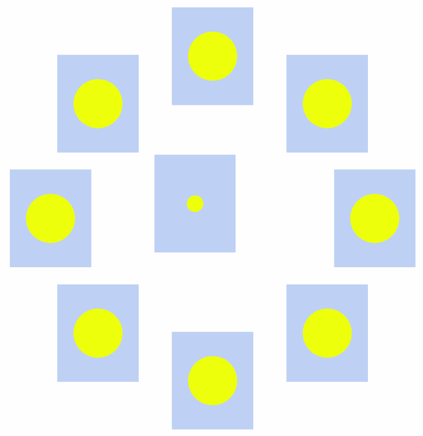
Example of using revolution
* This example shows how to use the REVZ keyword to position holes.
GEOM
  MODU  0
    * Definition of used shapes for the volumes or holes
    TYPE  1  BOX  30  30  20
    TYPE  2  BOX   5   6   4
    * Definition of the volumes or holes
    VOLU  1  0  1  m1    0  0  0
    * Create a hole
    HOLE  1  1  2  hole1   20  0  0


    * Following holes are set with the same x, y and z values than the previous
    * one. Revolution movement is added to change their positions.
    HOLE  2  1  2  hole1   20  0  0  REVZ  AZIM    45
    HOLE  3  1  2  hole1   20  0  0  REVZ  AZIM    90
    HOLE  4  1  2  hole1   20  0  0  REVZ  AZIM   135
    HOLE  5  1  2  hole1   20  0  0  REVZ  AZIM   180
    HOLE  6  1  2  hole1   20  0  0  REVZ  AZIM   -45
    HOLE  7  1  2  hole1   20  0  0  REVZ  AZIM   -90
    HOLE  8  1  2  hole1   20  0  0  REVZ  AZIM  -135
    * Create another hole
    HOLE  9  1  2  hole1   20  0  0  REVZ  AZIM   140  COLA  45  DIST  0.2
  ENDM

  MODU  hole1
    * Definition of the shape of the external volume (it must be the same shape
    * than the one that has been used for the hole of the module 0)
    TYPE  1  BOX   5. 6. 4.
    VOLU  1  0  1  m2   0. 0. 0.

    TYPE  2  SPHE  3.
    VOLU  2  1  2  m3   0. 0. 0.
  ENDM

ENDG

PAINT X 0. COLO ( m1 WHIT ) ENDP
PAINT Y 0. ENDP
PAINT Z 0. ENDP

STOP
Output of the example against the X-Y axis:
Output of the example against the Y-Z axis:

ROTA
The ROTA keyword changes the orientation of a volume/hole.
Its syntax allows specifying the number and order of successive rotations.
Successive rotation axes are identified by the values X, Y or Z.
The X, Y or Z axis of order n corresponds to the resulting transformation after the (n-1) previous rotations.
If the reoriented entity is:
a volume, its content is not modified.
a hole, the entire content of the module within the hole undergoes reorientation.
ROTA n e1 θ1 (..) ei θi (..) en θn
Input parameter |
Description |
|---|---|
n |
The number of successive rotations |
ei |
The axis of the i-th rotation (the authorized values are X, Y and Z) |
θi |
The angle relative to the i-th rotation (in degrees) |
The following examples show how to use the ROTA keyword.
Example n°1 using ROTA

|
GEOM
MODU  0
  TYPE  1  …
  TYPE  2  …  ROTA  1  Z  45
  TYPE  3  …
  VOLU  1  0  1  …
  VOLU  2  1  2  …
  VOLU  3  2  3  …
ENDM
ENDG
|
Example n°2 using ROTA
In this case, the rotation is applied to the external volume of the module and also to its entire content.

|
GEOM
MODU  0
  TYPE  1  …
  VOLU  1  0  1  …  …
  TYPE  2  …  ROTA  1  Z  45
  HOLE  1  1  2  1  …
ENDM
MODU  1
  TYPE  1  …
  VOLU  1  0  1  …
  TYPE  2  …
  VOLU  2  1  2  …
ENDM
ENDG
|
Example n°3 using ROTA
This example illustrates the code behaviour when multiple ROTA keywords are
used at several levels of the geometry description. The ROTA keywords are applied
to the shapes of the holes containing the modules.
The rotation is applied to the entire content of each Module, regardless of its level in the description.
The rotation applied to module 2 is therefore the combination of the rotation of module 1 described in module 0 followed by the
rotation of module 2 described in module 1.

|
GEOM
MODU  0
  TYPE  1  …
  VOLU  1  0  1  …  …
  TYPE  2  …  ROTA  1  Z  45
  HOLE  1  1  2  1  …
ENDM
MODU  1
  TYPE  1  …
  VOLU  1  0  1  …
  TYPE  2  …  ROTA  1  Z  -15
  HOLE  2  1  2  2  …
ENDM
MODU  2
  TYPE  1  …
  VOLU  1  0  1  …
ENDM
ENDG
|
Note
Rotational movements are always applied counterclockwise;
The rotation operator cannot rotate an external volume; instead the user must rotate the hole.